Rmcpherson
New member
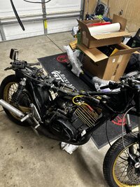
picked up this '73 RD350 with presumably a 400 motor and a Daytona front end as it was listed as a '79 RD400, but upon further investigation into the title and frame i determined it was a 73'.
I plan on this being a full frame-up build, cutting off excess tabs on the frame and powder coating it, reworking the cafe look, electronic ignition conversion and much more. As per the previous owner, Aaron's desire not to remove the cool aftermarket parts, I'm planning on keeping all the old-school DG parts on it, but want to put my flair on it. I may try adapting the old d.i.d front wire wheel after rebuilding it to a modern set of forks but undecided on that. exhaust will probably get powdercoated too since the coating on the top is long gone.
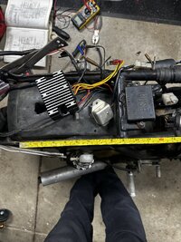
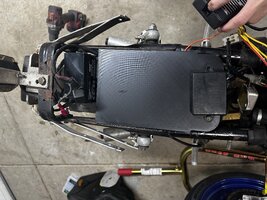
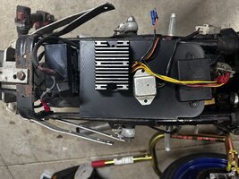
Current things i'm working on is cleaning up what is currently on the bike, fixing some of the original wiring, pulling off the rear fender liner as it doesn't do the frame lines any justice. I'm also working on designing and 3-d printing an electronics mount tray for under the rear tail section to help tidy up and clean up the wiring, although that might not be the final location depending on what rear tail section i go with, if i don't attempt to fiberglass my own design (which would be a first and big learning experience) I also need to fabricate some block-off plates and get a leakdown tester to see if i need to reseal this engine before going any further.
I plan on this being a full frame-up build, cutting off excess tabs on the frame and powder coating it, reworking the cafe look, electronic ignition conversion and much more. As per the previous owner, Aaron's desire not to remove the cool aftermarket parts, I'm planning on keeping all the old-school DG parts on it, but want to put my flair on it. I may try adapting the old d.i.d front wire wheel after rebuilding it to a modern set of forks but undecided on that. exhaust will probably get powdercoated too since the coating on the top is long gone.
Current things i'm working on is cleaning up what is currently on the bike, fixing some of the original wiring, pulling off the rear fender liner as it doesn't do the frame lines any justice. I'm also working on designing and 3-d printing an electronics mount tray for under the rear tail section to help tidy up and clean up the wiring, although that might not be the final location depending on what rear tail section i go with, if i don't attempt to fiberglass my own design (which would be a first and big learning experience) I also need to fabricate some block-off plates and get a leakdown tester to see if i need to reseal this engine before going any further.